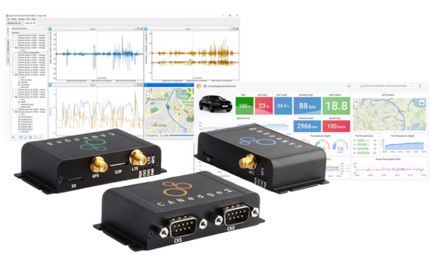
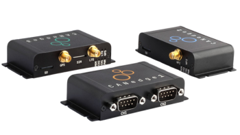
Using radio waves as slip ring replacement
Wireless as a reliable and wear-free option for data communication
EtherNet/IP and PROFINET are two protocols that utilize and add value to standard ethernet technology. Speed is often mentioned as a key benefit of PROFINET, while interoperability often goes into the EtherNet/IP column. Yet when it comes to one over the other, it's not so black and white. For product design and development, you may want to hedge your bets and support both.
Join us for our free webinar on How To Build A Better PROFIBUS Network Using ComBricks.
The world’s first time-sensitive networking (TSN) testbed is being developed in a collaborative effort to change network infrastructure so that it will enhance the Industrial Internet of Things (IIoT). As this develops, it is essential that Industry 4.0. Machine designers, builders, and users have reliable and secure access to smart edge devices. This will force the current, standard network technologies to transform in an effort to meet the requirements of the next generation of industrial systems.
his is a brief tutorial on how to operate the Procentec PROFIBUS Troubleshooting Toolkit Ultra Plus. For this tutorial, the PROFIBUS Troubleshooting Toolkit Ultra Plus is used. The PROFIBUS Training Kit will also be utilized; this is used for our troubleshooting and maintenance training using the ProfiTrace tools. In the PROFIBUS Training Kit, there is a PLC in the bottom of the case as well as five devices in the inner lid of the case. The last thing we will use is a Windows PC that is running ProfiTrace software.
The last part that is included in the troubleshooting kit Ultra Plus is the tab called “Topology,” which is located directly to the right of the bar graph tab. This can be used to calculate the topology, which is basically a drawing of the instillation. It tells the user who is connected to who in this daisy chain of PROFIBUS cables. When starting this up, it is important that the user selects where on the bus they are connected. In this case, we plugged the ProfiCore Ultra onto the PG connector on the PLC/master. So on the drop down menu, we would select master.
The next thing we will take a look at is the “Bar graph” tab, which is directly to the right of the ScopeWare one. The bar graph is measuring the amplitude of the signal coming from each device. On the graph, there is the signal and address on the far left in which the ProfiCore Ultra is connected to in order for it to be the strongest. Devices further away have a little bit less strength in signal.
Most problems in PROFIBUS are caused by physical layer problems. This essentially means there are cabling issues such as terminating resistors, shielding, rounding, and EMC. Things like this can cause problems with the high speed data communication cable, which is the PROFIBUS cable. One of the important tools in this program is called “ScopeWare,” which can be accessed on the upper left corner of the screen directly to the right of the ProfiTrace tab.
Another thing that can be done with ProfiTrace is to look at the messages that are being sent on the bus. To access these messages, click on the “Messages” tab that is above the matrix. This will be in line with the live list and statistic tabs that we have previously used.
When looking at the live list on the main screen, the user is able to see real time updates of what is going on. If the user had just walked up to the instillation and saw that all of the devices are green, they would assume that there is nothing wrong with the instillation. In reality, they would be seeing a real time representation of what is going on right now.
Get our monthly newsletter for product and technology updates