What Is CAN? A Practical Guide for Control Engineers and System Integrators
Your complete resource for understanding, selecting, and implementing CAN systems
Holiday Hours Notice: We will close at noon CT on Friday, May 22, resuming business on Tuesday, May 26. Orders placed after 11 AM CT on May 22 will be processed on May 26.
View full holiday schedule
Grid Connect can customize or produce a product based on our technology that fits your requirements.

Quickly and effectively implement your partial or complete, networking or embedded product.

We specialize in solving challenging IoT problems in demanding environments. No matter your application requirements.
Your complete resource for understanding, selecting, and implementing CAN systems
Whether you're designing a system from scratch or upgrading legacy equipment, Controller Area Network (CAN) remains a reliable, low-cost solution for industrial communication.
Originally developed by Bosch for automotive networks, CAN has expanded into industrial automation, heavy equipment, municipal infrastructure, and beyond - thanks to its noise resistance, real-time performance, and simplified wiring.
From a networking perspective, CAN operates at the lower layers of the OSI model, specifically the data-link layer (Layer 2) and the physical layer (Layer 1). It defines how bits are transmitted on the bus and how messages are framed, prioritized, and checked for errors. This guide provides a practical foundation to working with CAN - from choosing the right adapter to integrating it into modern or legacy systems.
At its core, CAN is a two-wire, multi-master network protocol that allows microcontrollers and devices to communicate without a host computer. In practice, this means that individual electronic components - such as sensors, actuators, and controllers - can send and receive messages to each other directly over just two shared wires. Each device listens to the network and can transmit information when the line is free, making the system both efficient and resilient.

This setup eliminates the need for a central computer to coordinate communication, which reduces complexity and potential failure points.
For example, in a modern vehicle, the engine control unit (ECU) can talk to the transmission, the brakes, and even the dashboard indicators independently, ensuring real-time coordination and faster system response.

The simplicity of the wiring, combined with the robustness of the protocol, makes CAN ideal for environments where reliability, speed, and minimal wiring are critical.
When discussing CAN, there are a few terms and concepts that are important to familiarize yourself with. These include:


CAN has become a widely adopted communication protocol in many industries due to its simplicity, robustness, and efficiency. Like any technology, it offers distinct advantages as well as certain limitations depending on the application. Understanding the pros and cons of CAN helps engineers and system designers determine whether it's the right fit for their specific needs.
For a deeper dive into real-world use cases and detailed comparisons, check out this post: CAN Network Protocol: Pros, Cons, Applications.
As CAN technology has evolved to meet the growing demands of different applications, several variations have emerged, each offering unique capabilities. Two key distinctions to understand are the difference between Standard and Extended CAN, which relates to how messages are identified, and Classic CAN vs CAN FD, which affects data capacity and speed. These variations impact everything from network design to device compatibility and performance.
While many systems use what's known as Standard CAN, there's also a variation called Extended CAN designed for more complex networks. Both use the same fundamental communication method and can coexist on the same bus, provided nodes support both formats. Extended CAN allows for a much larger range of message identifiers—making it ideal for systems with many devices or data types - like commercial vehicles or industrial networks.
In contrast, Standard CAN is simpler and more efficient for smaller networks with fewer nodes. Understanding the difference between these two formats ensures your system is designed with the right balance of performance, scalability, and message clarity.
| Feature | Standard CAN | Extended CAN |
|---|---|---|
| Identifier Length | 11 bits | 29 bits |
| Max. Number of IDs | 2,048 (211) | 536,870,912 (229) |
| Format Compatibility | Supported by all CAN controllers | Requires CAN 2.0B-compatible controllers |
| Bus Load Impact | Slightly lower (shorter messages) |
Slightly higher (longer headers) |
| Use Case | Simpler systems, smaller networks | Complex systems with many nodes or message types |
CAN FD (Flexible Data-rate) is an advanced version of the original CAN protocol, created to meet the growing demand for faster, higher-capacity data communication in modern vehicles and industrial systems.
Unlike Classic CAN, which is limited to 8 bytes per message and a fixed data rate, CAN FD supports payloads up to 64 bytes and allows for increased bit rates during the data phase.
It also includes additional control bits—such as EDL (Extended Data Length) and BRS (Bit Rate Switch)—to enable these enhancements.
CAN FD improves overall bandwidth and efficiency without changing the physical layer - meaning it can operate on existing CAN hardware with upgraded controllers. This makes it ideal for applications requiring larger data transfers, like advanced driver-assistance systems (ADAS), over-the-air updates, or sensor fusion.
While Classic CAN remains useful for simpler control messages, CAN FD is designed to future-proof CAN networks for more complex and data-intensive environments.
| Feature | Classic CAN | CAN FD |
|---|---|---|
| Max Data Payload | 8 bytes | 64 bytes |
| Data Rate | Up to 1 Mbps | Up to 8 Mbps (data phase only) |
| Frame Structure | Fixed data rate throughout | Separate arbitration and data phase speeds |
| Error Handling | Standard | Enhanced error detection with improved CRC |
| Compatibility | Widely used, legacy systems | Requires CAN FD-compatible controllers |
| Use Case | Basic control and monitoring | Data-intensive applications (e.g., ECUs, sensors, software updates) |
Although CAN provides a robust physical and data-link layer with efficient arbitration and error handling, it doesn't prescribe how application-level data should be structured or interpreted. This lack of standardization can pose challenges when building scalable or interoperable systems involving multiple vendors or complex coordination.
To bridge this gap, higher-layer protocols are often implemented on top of CAN to define message formats, device profiles, and network management behaviors. These protocols – CANopen, J1939, UDS, OBD2, and others – extend CAN's utility by enabling structured, deterministic communication tailored to specific domains and application requirements.
Let's take a closer look at some of the most widely used protocols, how they work, where they're used, and what sets them apart.
| Feature | J1939 | CANopen | UDS (on CAN) | OBD2 | LIN (Local Interconnect Network) |
|---|---|---|---|---|---|
| Governing Body | SAE (Society of Automotive Engineers) | CAN in Automation (CiA) | ISO (14229) | SAE, ISO | ISO (17987) |
| Primary Use Case | Heavy-duty vehicles, agriculture, commercial | Industrial automation, embedded systems | Vehicle diagnostics, ECU programming | Vehicle diagnostics (emissions, fault codes) | Low-cost in-vehicle communication |
| CAN Identifier Type | 29-bit (extended) | Mostly 11-bit | Depends (often 11-bit or 29-bit) |
Varies by implementation (CAN or ISO 9141, etc.) |
Typically 8-bit identifiers |
| Data Framing Limit | 8 bytes (classic CAN) |
8 bytes (classic CAN) |
8 bytes (uses ISO-TP for larger frames) |
8 bytes (on CAN) |
8 bytes |
| Transport Protocol | BAM, CMDT | SDO, PDO, domain transfers | ISO-TP | Uses ISO-TP on CAN | LIN Transport Layer (optional) |
| Communication Model | Broadcast (PGNs), peer-to-peer (CMDT) |
Client-server (SDO), producer-consumer (PDO) |
Request-response | Request-response | Master-slave |
| Device Addressing | 8-bit Source Address (0–253) |
Node ID (1–127) | CAN ID or extended addressing byte | OBD address 0x7DF (broadcast), or 0x7E0–0x7E7 | 1 master, up to 16 slaves |
| Standardized Data Definitions | Yes, via PGNs and SPNs | Yes, via device profiles | Limited; mostly manufacturer-specific | Yes, standardized PIDs | Limited, based on signal tables |
| Heartbeat/Health Monitoring | No explicit heartbeat; health via PGNs | Yes (heartbeat messages) |
Supported via session control/status | Via response/status PIDs | Yes, via schedule table |
| Diagnostics Support | Some via PGNs | Limited | Full diagnostic suite (DTCs, ECU ID, etc.) |
Standardized diagnostics (mode 01–09) |
Basic diagnostics only |
| Firmware Update Support | Yes (via transport protocols) |
Yes (via SDO/domain objects) |
Yes (dedicated services) |
Supported (e.g., mode 08) |
Limited |
| Scalability | High (fleet and OEM support) |
Moderate to high | High (manufacturer controlled) |
Moderate (regulated use case) |
Low to moderate |
| Typical Industries | Automotive, agriculture, construction | Factory automation, medical, lifts, energy | Automotive diagnostics, aftersales service | Automotive service and inspection | Body electronics (windows, mirrors, HVAC) |
To explore how these protocols function in real-world applications, check out our in-depth webinar CAN Higher Layer Protocols - J1939, CANopen, UDS or dive into practical insights in our companion guide, CAN Higher Layer Protocols Q&A.
CAN is widely used across a range of industries. Engineers, integrators, and system designers rely on it every day to enable reliable communication between devices in complex systems. Here are some of the most common environments where CAN can be found:
To connect your PC, embedded system, or controller to a CAN network, you'll need the right hardware interface. From USB adapters to gateways and data loggers, each option serves different development, testing, or deployment needs.
Many modern CAN interfaces support variants such as CAN FD and Extended CAN identifiers (29-bit), enabling higher data throughput and scalability for complex systems. Be sure to verify compatibility based on your specific application requirements.
To quickly shop by category, check out our CAN overview page.
Shop all CAN productsCAN to USB adapters allow a computer to interface directly with a CAN network through a USB connection. They're commonly used for development, debugging, and diagnostics, especially in lab or field environments where flexibility and quick setup are important. Learn more about their capabilities and use cases with our guide to CAN to USB adapters.
Shop all CAN to USB Adapter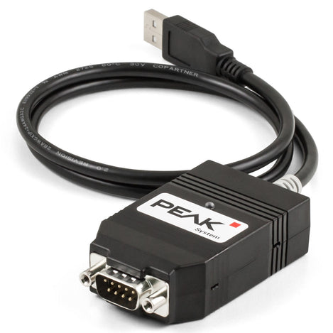
CAN PC interfaces allow desktop or industrial computers to connect directly to a CAN network using formats such as PCI, PCIe, or Mini PCIe. These interfaces are ideal for high-performance applications such as real-time control, data logging, or automated testing where low latency and consistent throughput are critical.
Shop all CAN PC Interfaces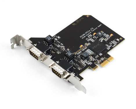
CAN routers and gateways manage communication between multiple CAN networks or between CAN and other protocols such as Ethernet, Modbus, or RS-232. These devices are essential in complex, multi-bus systems where message routing, isolation, and protocol bridging are required for reliable system coordination.
Shop all CAN Routers & Gateways
CAN I/O modules and sensors expand a CAN network by adding physical inputs and outputs, such as analog signals, digital switches, relays, temperature, or pressure data, directly into the CAN bus. These modules allow controllers to monitor or control real-world processes without needing separate wiring or protocols.
Shop all CAN I/O Modules
CAN couplers and converters are used to adapt or isolate CAN signals to meet the specific requirements of different systems. These tools are especially useful in mixed-system environments, long-distance installations, or retrofit projects where electrical compatibility and signal integrity are critical.
Shop all CAN Couplers & Converters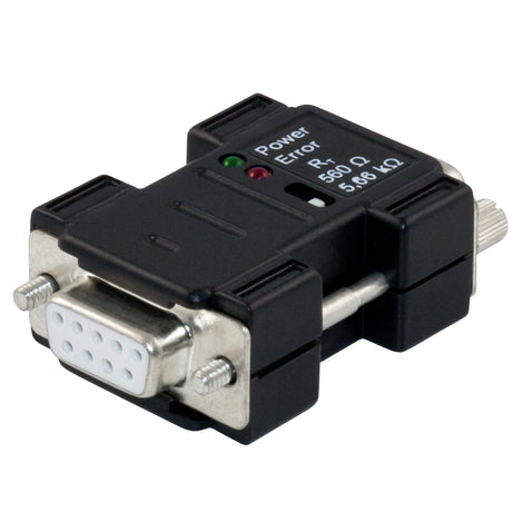
CAN diagnostic tools are used to monitor and analyze real-time traffic on a CAN network, making them essential for development, troubleshooting, and system validation. They allow engineers to view message frames, track errors, and interpret live data from nodes on the CAN bus.
Shop all CAN Diagnostics Tools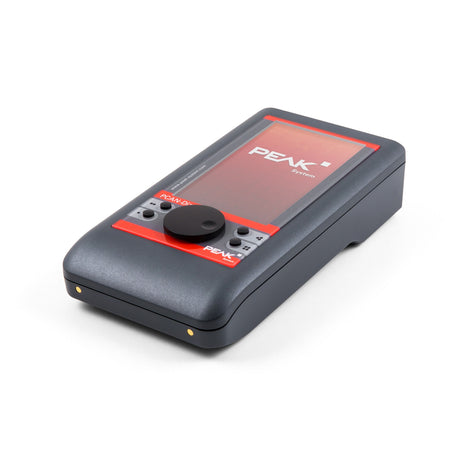
CAN data loggers continuously record CAN traffic over time, enabling long-term analysis for field testing, vehicle validation, and performance monitoring. These devices either store data locally or transmit it remotely for later review, helping engineers capture intermittent faults or evaluate system behavior under real-world conditions. To learn more, check out our CAN data logging explainer and our guide to choosing the right CANedge device.
Shop all CAN Data Loggers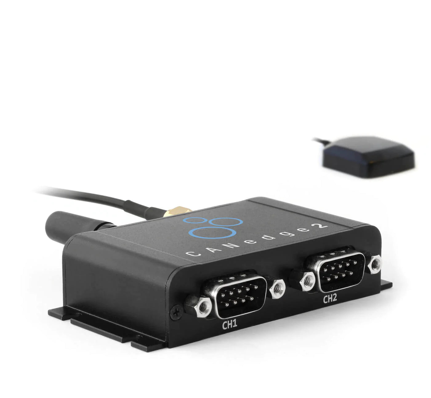
CAN software is the interface that brings your CAN hardware to life, enabling configuration, communication, debugging, and analysis across the entire system. It plays a critical role in both development and deployment, offering visibility into traffic, control over messages, and tools for automation.
If you're using a USB-to-CAN adapter or a PCI-based interface, most solutions include free basic software, such as Peak's PCAN-Basic and PCAN View, to help you get started.
For more advanced capabilities like real-time monitoring, filtering, scripting, and simulation, software such as PCAN-Explorer 6 offers a robust platform, and a free 30-day trial to explore its full potential.
Not sure where to begin? Watch our introductory webinar to see PCAN-Explorer in action.
Shop CAN Software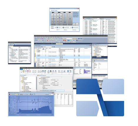
Custom CAN options are ideal when off-the-shelf products fall short, and you need a solution that aligns precisely with your requirements or environment.
Whether it's a custom connector layout, specialized firmware, enclosure design, or cloud connectivity, Grid Connect can tailor every element to fit your exact use case.
With deep experience in both CAN and networking technologies, our team provides the flexibility and engineering support needed to create reliable, scalable, and fully certified custom CAN solutions – delivered on time and built to last.
Explore Custom Options
Running into issues with your CAN setup? You're not alone – and you're not on your own.
At Grid Connect, we've spent more than 20 years helping engineers resolve technical challenges in real-world CAN applications. As an ISO 9001:2015 certified company and the official North American distributor for trusted CAN brands like PEAK, IXXAT, and CSS Electronics, we're known for delivering not just hardware, but expert guidance. Our team takes the time to understand your system and offer practical, application-specific solutions.
If you're looking for deeper insights into resolving CAN issues, explore our guide on how to diagnose a CAN network, watch our practical CAN troubleshooting webinar, or browse our CAN Bus Diagnostics Q&A.
Below are some common problems and quick fixes to get you started.
| Problem | Cause | Solution |
|---|---|---|
| No communication | Improper termination | Ensure 120Ω resistors at each end |
| Noise or erratic data | Poor shielding | Use twisted pair + proper ground |
| Message conflicts | ID collisions or baud mismatch | Check arbitration + bit rate |
Our knowledgeable engineers and in-depth support resources are here to assist you.
You'll find manuals, drivers, and documentation for every product right on its page, just scroll to the Documents & Drivers section.
And if you need hands-on assistance, our team is ready to help troubleshoot and recommend the right solution.
Contact SupportStay up-to-date with the latest tips, product updates, and expert guidance from our team. Browse our most recent blogs, how-to articles, and webinars to keep your CAN knowledge sharp and your projects moving forward.

by Grid Connect Team

by Grid Connect Team

by Grid Connect Team
Whether you're building a test setup, deploying an industrial system, or integrating CAN into an existing product, Grid Connect offers the tools and expertise to help you get it right.
Our selection includes trusted hardware from brands like PEAK, IXXAT, and CSS Electronics, supported by engineers who know the technology inside and out.
With compatibility across Windows and Linux, and guidance available for setup, debugging, and integration, we're here to make your project successful from start to finish.
