$347.00
PCAN Explorer 7 is here! Request your upgrade today.

$1,790.00
SKU: GC-CAN-ROUTER-PRO-FD-6X
MPN: IPEH-002220
Manufacturer: Peak System Technik
Stock Status: In stock
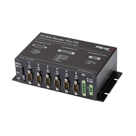
The PCAN-Router Pro FD has 6 channels, 1 analog input and 4 digital I/O. With the ability to link or merge data traffic between CAN FD and classic CAN buses, the PCAN-Router Pro is ideal for testing or data logging applications.
Router Usage
To use the PCAN-Router Pro FD as a Router, it needs to be programmed for specific routing applications using an included development package with GNU compiler for C and C++. Firmware is transferred to the unit using the PCAN-Flash tool over one of the CAN channels. A PCAN-USB is recommended to interface the PC running the PCAN-Flash tool to connect the PC to the router’s CAN channel. Sample code is included for various routing applications such as message forwarding or recording, and how to connect disparate types of CAN networks (classic CAN and CAN FD) and to set bit rates.
Data Logger Usage
The PCAN-Router Pro FD comes out of the box configured as a data logger for recording CAN data and error frames. CAN messages can be recorded on the internal memory or on an inserted SD card. Logged data can be read out via the USB connection. Modifications to the Data Logging function are accomplished with a simple text based configuration file. Settings such as bit rates, listen-only mode, sleep mode, remote start/stop remote control of logging, are all available through the config file. With this configuration, the data flow of test benches and production plants can be managed, monitored, and controlled.
Data Logger Recording
On delivery, the PCAN-Router Pro FD is equipped with firmware for recording CAN and CAN FD data traffic. The messages of all six CAN channels can be stored on the internal eMMC memory or on an inserted SD card (not included – up to 1TB). The SD card data can be accessed via a USB connection.
Data Logger Configurations
Users can configure the CAN message recording with a text file without any
programming knowledge. Various options are available:
Package contents include:
• PCAN-Router Pro FD in aluminum casing
• Mating connectors for I/O and power
• USB connector cable
• Windows® development package with GCC ARM Embedded, flash program, and programming examples
• Conversion software PEAK-Converter for Windows® 10 (32/64-bit)
• Manual in PDF format
PCAN-Router Pro FD Manual
PCAN-Router Pro FD package
All resources needed to develop a custom firmware, the flash program PEAK-Flash for the firmware upload, short instructions, and programming examples
PEAK-Flash
Easy-to-use tool for updating the firmware of PEAK-System hardware products as well as CAN and LIN adapters
Certifications
EMV, RoHS2
Channels
6 High-speed CAN channels (ISO 11898-2)
Connector(s)
Controller(s)
Microcontroller STM32F765NIH6 (based on Arm® Cortex® M7)
Data Rate
Dimensions
190 x 104 x 55 mm
Indicators LED
CAN channels, memory cards, and power supply
Input/Output
Memory
MPN
IPEH-002220
Operating System
Windows 10, 8.1, or 7 (32/64-bit)
Power Supply
8 - 32 V power supply, protection against overvoltage and reverse polarity
Security/Protection
IP20
Specification
Comply with CAN specifications 2.0 A/B and FD
Standards
CAN FD support for ISO and Non-ISO standards
Temperature Range
-40°C to +85°C (-40°F to +185°F)
Transceiver
NXPTJA1043 CAN transceiver with wake-up

$347.00

$830.00

$451.00
Please fill out the information below and our sales team will respond within 1 business day.
What you can expect from Grid Connect: